Sunday, February 20, 2011

The Process Control Loop

Hi, its me again and I am about to tackle a very important framework in the field of Instrumentation. Assuming you already have read my post regarding what a process control is and what are the parameters involved in this process. We are now going to learn how these parameters are meet in a process control loop.


First we need to know what are the major components a traditional control loop has. 

1. The controller
2. a sensor/transmitter
3. a final control element

Click and animate in larger view
A controller that seeks to maintain the measured process variable (PV) transmitted by a sensor or a transmitter. and a the final control element  that implements in real life the decision or solution taken by the controller. Common examples of a final control element are control valves, relay switches and variable frequency drive to name a few.

To design and implement a controller, we must:
  • have identified a process variable we seek to regulate (e.g., room temperature like the example mentioned by wiki), be able to measure it with a sensor, and be able to transmit that measurement as an electrical signal back to our controller, and
  • have a final control element  that can receive the controller output (CO) signal, react in some fashion to impact the process (e.g., a control valve moves or a relay switch turns on/off), and as a result cause the process variable to respond in a consistent and predictable fashion.
As shown below (click to animate and enlarge), the home heating control system described by wiki can be organized as a traditional control loop block diagram. Block diagrams help us visualize the components of a loop and see how the pieces are connected.

A home heating system can be a simple on/off control or a proportional control by adjusting the amount of hot fluid by throttling a control valve. Nevertheless, we introduce the idea of control loop diagrams by presenting a home heating system in the same way we would a more sophisticated commercial control application.

Click and animate in larger view
Starting from the far right in the diagram above, our process variable of interest is the house temperature. A temperature sensor, such as a thermistor in a modern digital thermostat, measures temperature and transmits a signal to the controller.

The measured temperature PV signal is subtracted from set point to compute controller error, e(t) = SP – PV. The action of the controller is based on this error, e(t).

In this example,home heating system, the controller output feds a varying or proportional milliamp signal to a variable operating solenoid or servo valve  (our Final Control Element)that controls the flow of hot water .

As the energy output of the furnace rises or falls, the temperature of our house increases or decreases and a feedback loop is complete. The important elements of a home heating control system can be organized like any commercial application:

  • Control Objective: maintain room temperature at (SP) in spite of disturbances
  • Process Variable: room temperature
  • Measurement Sensor: temperature sensor,Thermistor
  • Measured Process Variable (PV) Signal: signal transmitted from the thermistor 
  • Set Point (SP): desired room temperature
  • Controller Output (CO): signal to the variable operating solenoid valve
  • Final Control Element (FCE): variable operating solenoid valve to control hot water flow
  • Manipulated Variable: hot water flow rate to chamber
  • Disturbances (D): heat loss from doors, walls and windows; changing outdoor temperature; sunrise and sunset; rain...
With the loop closed as shown in the diagrams, we are said to be in automatic mode and the controller is making all adjustments to the Final Control Element. If we were to open the loop and switch to manual mode, then we would be able to issue controller output commands through buttons or a keyboard directly to the Final Control Element. Therefore:
  • open loop = manual mode
  • closed loop = automatic mode
This control loop block diagram will be a frame work to more simple process control and even to more sophisticated commercial control application. I hope you learned something. jump in to more of my post or check me out if I'm online or check me out in good game studios playing poker. lol


Tuesday, February 15, 2011

How does a 5/2 way directional valve work?


This instrument is not new to me. Since We started our pneumatics class on my third year in college, I already had the pleasure to meet this instrument. We even had to use this almost everyday, during our laboratory exercises. Its always present in all our 
pneumatic and hydraulic trainers. How does this stuff really work? 


A valve is a device that regulates the flow of fluid (gases, liquids,fluidized solids, or slurries) by opening and closing or partially obstructing passage ways 1.

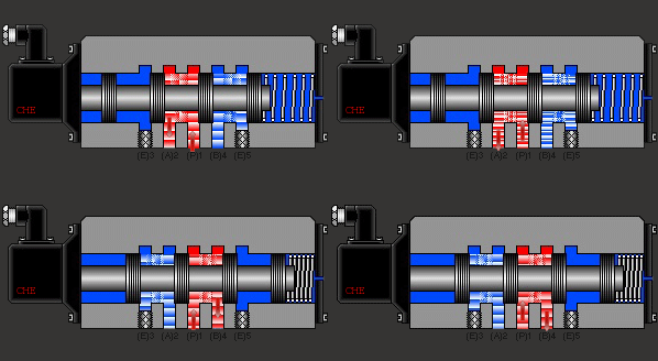
A 5/2 way directional valve from the name itself has 5 ports equally spaced and 2 flow positions. It can be use to isolate and simultaneously bypass a passage way for the fluid which for example should retract or extend a double acting cylinderThere are variety of ways to have this valve actuated. A solenoid valve is commonly used, a lever can be manually twist or pinch to actuate the valve, an internal or external hydraulic or pneumatic pilot to move the shaft inside, sometimes with a spring return on the other end so it will go back to its original position when pressure is gone, or a combination of any of the mention above.


In the Illustration given, a single solenoid is used  and a spring return is installed in the other end. The inlet pressure is connected to (P)1. (A)2 could possibly be connected to one end of the double acting cylinder where the piston will retract while (B)4 is connected to the other end that will make the piston extend. The normal position when the solenoid is de-energized is that the piston rod is blocking (B)4 and pressure coming from (P)1 passes through (A)2 that will make the cylinder normally retracted. When the solenoid is energized, the rod blocks (A)2 and pressure from (P)1 passes through (B)4 and will extend the cylinder.and when the solenoid is de-energized, the rod bounces back to its original position because of the spring return. (E)3 and (E)5 is condemed or used as exhaust.

See how cool the combination of Electronics and Pneumatics is? There will be alot more illustrations on pneumatics and hydraulics instruments coming soon that you should'nt missed. I hope you enjoy reading. 


Friday, February 11, 2011

Instrumentation In Process Control

Instrumentation is defined as the art of science in measurement and control 1

Instruments can be found anywhere, they can be found in laboratories, refineries, factories, vehicles and even at school and in our homes too. For example, the faucet which Sarah quoted as the saddest instrument controls the flow of water flowing to the kitchen sink or a glass. In western homes  smoke detector is also a common instrument.

In the plant industries, Instrumentation is the art of measuring the value of some plant parameter, pressure, flow, level or temperature and supplying a signal that is proportional to the measured parameter. The output signal can then be processed by another instrument or equipment to provide indication, alarms or automatic control. There are a number of standard signals; however those common are the 1-5V and 4-20 mA electrical and electronic signal the 3-15 psi or 20-100 kPa pneumatic signal. I remember Engr. SalvaƱa always reminds us to remember this standards when we go and apply for a job. It helped though. Thanks to our hydraulics class instructor.

Output instrumentation includes devices such as solenoids, valves, regulators, circuit breakers, and relays. These devices control a desired output variable, and provide either remote or automated control capabilities. These are often referred to as final control elements when controlled remotely or by a control system.

Transmitters are devices which produce an output signal, often in the form of a 4–20 mA electrical current signal, although many other options using voltage, frequency, pressure, or ethernet are possible. This signal can be used for informational purposes, or it can be sent to a PLC, DCS, SCADA system, or other type of computerized controller, where it can be interpreted into readable values and used to control other devices and processes in the system.

Control Instrumentation plays a significant role in both gathering information from the field and changing the field parameters, and as such are a key part of control loops.


Thursday, February 10, 2011

What is Process Control?

First we need to understand what process control is and what are the important technical terms and parameters involve in this process.

Process control is a statistics and engineering discipline that deals with architectures, mechanisms and algorithms for maintaining the output of a specific process within a desired range as per wikipedia.

Wiki sited an example about heating up of a room temperature which is a process that has the specific, desired outcome to reach and maintain a temperature (e.g. 20°C) defined by you or a person inside the room and should be kept constant over time. You can always change the setting from time to time depending on what your body wants. Get the remote control and adjust the setting to your desired temperature.

In the example above,  the temperature is the process variable (PV) as shown on the picture at the left. At the same time, it is the input variable since it is measured by a thermometer and used to decide whether to heat or not to heat up the room as you prefer. The desired temperature (20°C) is the setpoint (SP). The state of the heater, for example the setting of the valve allowing hot water to flow through it or in the case of simple on-off control, turning the heater off and on  is called the manipulated variabl(MV) since it is subject to control actions. The first instant is an example of a Proportional control since the opening of the valve is proportional to the needs of the users of the room. There are other types of control such as Derivative and Integral or a combination of the two incorporated with Proportional or what we call PID.  This are all common in controlling other parameters such as pressure, flow and level of a material (liquid or solid). 

A commonly used control device called a programmable logic controller, or a PLC, is used to read a set of digital and analog inputs, apply a set of logic statements, and generate a set of analog and digital outputs. Using the example in the previous paragraph, the room temperature would be an input to the PLC. The logical statements would compare the setpoint to the input temperature and determine whether more or less heating was necessary to keep the temperature constant. A PLC output would then either open or close the hot water valve, an incremental amount, depending on whether more or less hot water was needed or just simply turn the heater off when the desired temperature is reached and turn it back on when a specified hysteresis is meet. Larger more complex systems can be controlled by a Distributed Control System (DCS) or SCADA system. Click here to know more about the general process control loop.

As a trainee, I find all this stuff cool and interesting. Although I already meet this terms during my college days, I failed to appreciate. Now that I'm finally given the chance to pursue what I have studied for and given all the resources and tools on the web. I'd say goodbye to papers and reports and say hello to the world of mechatronics and the world wide web.